Mercury Nest - Assembly
This is a step by step assembly guide for the Mercury Nest System
---
Package contents:
2 x Side panels
1 x Back panel with round cut-out
1 x Front panel with square cut-out
1 x Base panel
1 x Top panel with lid cut-out
1 x Lid panel
2 x Red acrylic light shields
1 x Screw pack + Hex tool
1 x Set of white fittings
1 x Large test tube
1 x Small test tube
UPDATE - Now shipping with 1 x plastic tool to easier hold the corner fixings
3 x Test tube entrance reducer rings (Small/Medium/Large)
1 x Cotton Wool Ball
---

Prepare for assembly
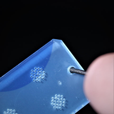
Please check each panel and remove any hole cutouts left from the laser cutting process. This is easily done by lightly pressing them out using the provided hex tool.

Next remove the protective film from both sides of each acrylic panel.

Step 1 - Corner Fixings
Please note it is important not to over-tighten any screws, as this can thread the fixings or crack the acrylic panels. Stop when you notice additional resistance when tightening.
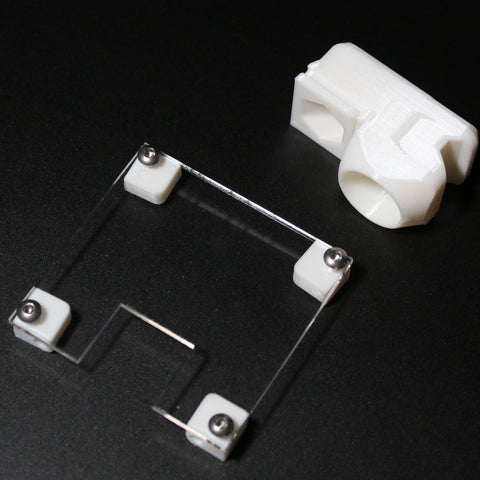
Gather 8 screws, both end panels and the white corner fixings. As seen below.

The fixtures are screwed in like below with the rounded corners facing toward the centre with the two screw openings facing out toward the corners.
PLEASE NOTE - We now include a small tool to easier hold the fixings


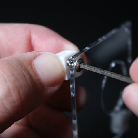
Hold the corner fixings in place.

Insert a screw and start to hand tighten.


Once the screw is inserted enough its easier to switch to holding the corner fixing with two fingers. Please note the screw does not need to be fully tightened. It should only be screwed in enough to hold the fixture in place but allow some movement. If it is tricky to tighten up at this point that is fine, as these will be fully tightened later.
After this you will have the corner fixtures in place like shown below. These should be slightly loose ready for tightening later.

Step 2 - Front panel assembly
Gather the front panel with the square cutout and the tube connector part.
Then slide the panel into place along the groove.

Slide it all the way down until it sits flush at the top.

Step 3 - Base panel
Gather the base panel as shown below

Slide the cutout into the groove as shown below.

The base panel will slide flush under the end panel.

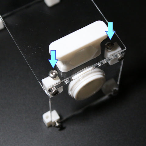
Turn the unit over and insert the screws as shown below. These do not need full tightening just yet.

Again it is easier to hold the white fixtures when tightening.

Step 4 - Base Stand
Now install the stand as shown below. These should be full tightened but please take care not to over tighten.

Step 5 - Rear end panel
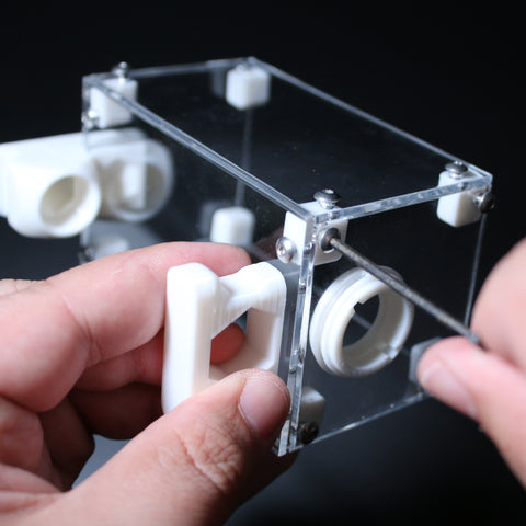
Gather the end panel with the round cutout and the two large rings.

Insert the thicker ring as shown below. Please note the white fitting has some notches on each side which slot into the cutouts.

Ensure the fitting is inserted from the correct side. The white fitting inner notches should be visible on the screw side of the panel

Now take the remaining ring. See pictures below before completing this step. This snaps into place over the inserted part. Ensure the widest part is pressed over the fitting. The best way to ensure no damage to the acrylic is to place the panel screw side down on a flat surface. Then start with holding one side down in place and then apply pressure working around. This is a tight fitting so a decent amount of pressure may be needed. Once it snaps into place ensure there is a flush seal all the way around.


Proceed to connect this end panel to the unit. Turn the unit upside down and rest the panel in place. Then insert the screws as shown below enough to hold in position. Do not fully tighten yet.

Step 6 - Side panels
Place the unit on its side and gather one of the side panels. Then apply screws to the 4 corners as shown below. Do not fully tighten.


Once one side is complete, flip the unit over and repeat for the other side.
Step 7 - Tightening
Once the side panels are in place it is now time to tighten up the joints. It is best to do this bit by bit rather than each screw at a time. Work your way around the module slowly tightening each screw. Stop when you notice more resistance than normal. Take care not to overtighten the screws.
Once all of the screws are tightened visually inspect all of the panels to ensure a flush seal all around.

Step 8 - Top panel
Place the lid on top and insert any remaining screws to fully seal the unit.

Once completed check all the seals to ensure flush.

Step 9 - Lid assembly
Position the lid panel on top of the lid part and screw together.

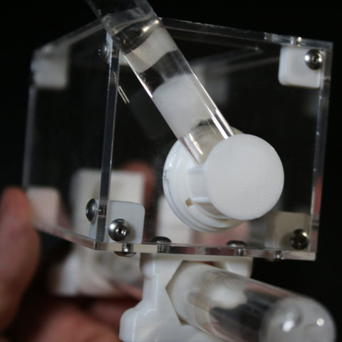
Step 10 - Test tube setup
Insert the large test tube as shown below. Ensure this is pushed in fully.

Now turn the unit upside down. Using the hex allen key or a pen, make a mark on the tube where the tube enters the stand. This will be used as a fill up guide.


Fill the tube with water. Avoid tap water if possible. Bottled spring water is the best option. If tap water is used, ensure this is boiled and then cooled to room temp. The colder the water, the more gasses it contains. By boiling water on the stove for 20 minutes, the water will degas and chlorine will evaporate.

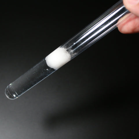
Now take the cotton ball and split into to halves

Push one half down the tube slowly until fully wet. Hold the tube fully vertical to avoid making air bubbles in the water

Ensure the cotton is nice and fully wet. If there was any excessive water pushed through this can be tipped out now.
Next is time to insert any chamber makers. Supplied is 3 different sizes depending on ant species. These are used to make the ants feel safer and more enclosed in a chamber. They also help keep humidity in the tube. It is best to insert the smallest size possible. Ensure the hole size is sufficient enough for your queen or largest ants to pass through.


Once complete insert the tube into place. Check this is fully inserted

Step 11 - Light Shield
Gather the two red screens and the white fittings as shown below.

These have been recently updated with a cutout to allow use of heat cables. They should be on the side closest to the opening of the test tube as shown below

Clip the fittings into the cutouts.


Slide the unit down on top of the screens. These will fit snug around the tube.

Next is to attach the stand base. Gather the fitting as shown below

Firstly ensure it is the correct way round. The cutout should be on the test tube side. Slide this into place but not all the way. Just into the correct alignment like shown below.

Flip the unit over and evenly press down on each of the top corners. This will ensure a level base and ensure there is no wobble in the unit.

Step 11 - Water Dispenser
Gather the small test tube, remaining cotton ball and tube fitting.
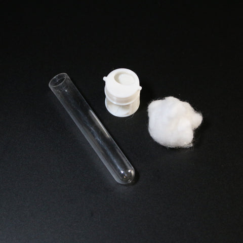
Fill the tube with water.
Bottled spring water is highly recommended.

Tear off a small amount of the cotton ball. Enough to loosely seal the tube.


Slot the tube into the fitting as shown below.

Connect to the unit. The dispenser needs to align with the port to be inserted

When aligned correctly proceed to insert as shown below.
Once fully inserted twist vertically to lock into place.

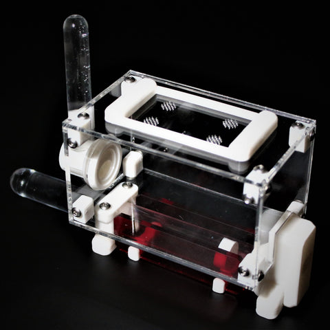
Congratulations. Your outworld is fully assembled.
Enjoy!